Alternatively, Alternators

Abstract—This paper concerns the functional principles of automotive alternator systems.

INTRODUCTION

Automotive alternator or charging systems are made up of three components: the Alternator, which is essentially an AC generator, a Voltage regulator and a 12V Battery. This paper will explore this simple system particularly as it relates to a 1982 BMW 320i Coupe.

II.

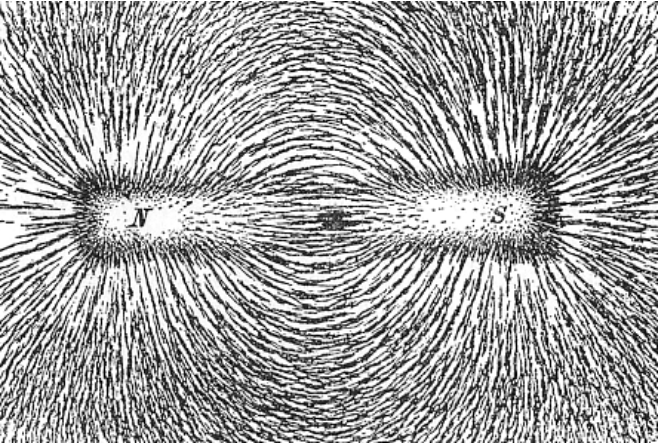
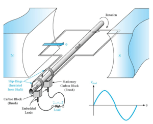
Alternators work on the principle of electromagnetism laid down in what is probably one of the top three most important concepts in electrical engineering: Faraday’s Law. Faraday’s Law states simply that when a coiled conductor  is exposed to a moving magnetic field, a current is induced in the conductor. More accurately, an electromotive force is created, which induces a current in the conductor. The force produced by the movement of the magnetic field within the coil is amplified by the number of turns in the coil, signified by the variable (N). Faraday’s law is shown in figure 1.

Screen Shot 2015-08-19 at 4.25.47 PM

Fig. 1, Faraday’s Law (Lenz’s Law)

This formula at its most basic level, describes the process by which mechanical energy (work) can be converted into electricity. This is exactly what an alternator does. It converts the energy output from the burning of gasoline (or diesel) into electricity to keep the car’s 12V, battery-powered electrical system topped off.

III.

Typically, an automotive alternator should output enough voltage potential to keep a 12V car battery at a voltage of approximately 14V. Testing of the charging system of the 1982 BMW 320i Coupe used as an example in this paper with a DMM reveals that the 320i’s alternator “outputs” approximately 13.5V. This is a bit low but, as stated before, an alternator converts mechanical energy to electrical energy. This BMW has a slowly failing in-tank fuel pump and a worn-out distributor bearing. It is also possible that there could be a pinhole vacuum leak somewhere in the intake manifold boot, which is a 33+ year old rubber part. All these variables add up to less than optimal engine performance, which translates to less than optimal mechanical energy output, which further translates to less than optimal alternator output. The 320i’s voltage output is displayed in figure 2.

Screen Shot 2015-08-19 at 10.31.21 PM

Fig. 2, Charging output of a 1982 BMW 320i alternator

The voltage output of the 320i’s alternator increases when the throttle is opened (fuel is injected into the engine). This is consistent with how an alternator is expected to perform. Alternator current output is proportional to rotations per minute of the alternator pulley, which is controlled by the engine’s power output. The faster the car is going, the more current is produced by the alternator. This concept is exemplified by the chart in figure 3 below.

Screen Shot 2015-08-19 at 10.31.34 PM

Fig. 3, Alternator Output – Amps vs Engine RPM

This is why, if a battery is flat, it can be recharged by a long (hour or more) drive. As previously stated, an alternator is designed to simply top-off battery charge but, given enough time under normal running conditions, an alternator will generate enough power to fully recharge a 12V battery.

However, this scenario is by no means ideal. An alternator is not designed for fully recharging a battery. It can simply be used to do so. Optimally, a dedicated battery charger that plugs into the main grid should be used to recharge a flat battery.

IV.

An alternator is essentially an AC generator so it consists of an armature, a magnetic pole, a commutator and a rotor shaft. An automotive alternator also features an interior cooling fan to dissipate the heat generated by spinning and producing electricity as well as a voltage regulator that distributes and controls the amount of current produced by the alternator that goes to the battery. Figure 4 is an exploded-view diagram of a Bosch alternator similar to the one on the 1982 BMW 320i used as an example in this paper. 

Screen Shot 2015-08-19 at 10.31.49 PM

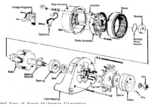
Fig. 4, Exploded-view Diagram of Bosch Alternator

The average alternator has five terminals. An S-terminal senses the battery voltage. The IG terminal is attached to the ignition switch that turns the voltage regulator on when the engine is cranked. Under nominal operating conditions, the L terminal closes the circuit to the battery warning light. The B terminal is the main alternator current output terminal, which is attached to the positive battery terminal. Finally, the F terminal is the full-field bypass for the regulator.

Batteries need a direct current. Because alternators are actually AC generators, they are fitted with a diode rectifier (or rectifier bridge) in order to convert the current before it gets sent to the battery.

V. CONCLUSION

Alternators produce an AC current that is rectified to DC and then sent off to charge the battery. The amount of voltage put on the battery is determined by a voltage regulator fitted to the alternator generator. The regulator determines when to deliver voltage and how much voltage is needed to be delivered to the battery.

Alternators are crucial automotive component that an engine will not run on its own without a properly functioning one.

When running, a car’s alternator should deliver a DC voltage of approximately 14V to the car’s battery. If this voltage is below the 14V threshold, it may be possible that the alternator is failing. In that case, it is advisable to immediately have the part replaced to avoid power loss while driving, which can be an incredibly dangerous scenario. It is also advisable for car owners to purchase name-brand alternators from quality parts makers like Bosch. Off-brand and discount alternators use low-quality parts to keep their overhead low and as a result, the inferior parts have a low lifespan. Buying quality parts will save money in the long run.

REFERENCES

HYPERPHYSICS. Faraday’s Law. [Online]. Available: http://hyperphysics.phy-astr.gsu.edu/hbase/electric/farlaw.html

MINEBEA. History of Brushless DC Motors. [Online]. Available: http://www.nmbtc.com/brushless-dc-motors/brushless-dc-motors/

OHIO ELECTRIC MOTORS INC. Permanent Magnet DC Motors. [Online]. Available: http://www.ohioelectricmotors.com/permanent-magnet-dc-motors-649

ALL STAR MAGNETICS. Neodymium Magnets. [Online]. Available: http://allstarmagnetics.com/index.php/neodymium_magnets

Fawwaz T. Ulaby, Eric Michielssen, Umberto Raioli, “Maxwell’s Equations for Time-Varying Fields,” in Fundamentals of Applied Electromagnetics, 6th ed. Prentice Hall Publishing

Nikola Tesla, “My Later Endeavors,” in My Inventions – The Autobiography of Nikola Tesla, New York, 1919

Gordon Tobias S.A.E., “Engine and Engine Overhall,” in Chilton BMW Coupes and Sedans 1970-88 Repair Manual, 1996, Haynes North America Inc.

The History and Principles of DC Machines

Abstract—This paper concerns the history and development of the modern DC electric generator and the scientific principles upon which electric machines are built.

INTRODUCTION

IT  was in the year 1831 that British scientist Michael Faraday discovered the principles of what we now call “induction.” He discovered that by coiling a  conductor around a ferrous ring and inserting a magnet into the center “donut hole” of the ring, he could induce a current in the coiled conductor. Faraday explained his discovery with a what he conceptualized as “lines of force,” which are demonstrably observable when a magnet is placed amidst a smattering of iron shavings as pictured in figure 1, but he was unable to express the idea in the scientific lingua franca of mathematics so his ideas were largely ignored by his peers. 

Screen Shot 2015-08-19 at 4.24.44 PM

Fig. 1, Magnetic Field Lines

That is, until 1861, when a young mathematician and physicist named James Maxwell came onto the scene and published his paper, “On Physical Lines of Force.” In the paper, Maxwell provided the mathematical “bricks” to flesh-out Faraday’s concept of induction. As indicated in figure 2, Maxwell’s “Faraday’s Law” states that an electromagnetic force (Vemf) is induced due to a change in magnetic flux (φ) over time, multiplied by the number of turns (N) in a conductive coil.

Screen Shot 2015-08-19 at 4.25.47 PM

Fig. 2 Faraday’s Law (More accurately Lenz’s Law)

The negative sign preceding number of turns (N) in Faraday’s law actually comes from Lenz’s Law, which came years after Faraday’s death. Lenz discovered that the direction of the induced EMF will oppose the change in magnetic flux. Before that, Faraday’s law simply stated that induced EMF would be equal to the change in flux over time. Lenz’s Law makes Faraday more accurate.

Faraday’s Law is an extremely important concept because it quantifies how mechanical energy can be converted into electricity. In the most basic terms, this is the entire concept behind the electric age that has afforded and allowed for the plush society humanity takes for granted today.

This paper will explore these concepts as well as the series of events that led to the electric-machine-powered world humanity lives in today.

II.

One of the, if not the first machines to take advantage of the concept of induction was, not surprisingly, conceived by Michael Faraday himself. Faraday invented a precursor to what is now known as a disc-rotor DC generator or “Dynamo.” He called his machine the “homopolar generator” (pictured in figure 3). Others dubbed it the “Faraday Disc” in the titular scientist’s honor. The Faraday Disc was essentially a hand-crank that spun a conductive disc through a horseshoe-shaped magnet. The movement of the disc between the poles of the magnet induced a current in the disc that traveled or radiated from its center to its edge, where it was then transferred through a spring-brush and redirected back into the disc’s center through its axle shaft.

Screen Shot 2015-08-19 at 4.26.03 PM

Fig. 3, Faraday Disc

Faraday’s invention was inefficient to put it nicely and was only capable of inducing low voltages. Others during the 1820s to 1850s also experimented with electric generator technology and Dynamo technology made stumbling, slow progress. The machines coming out on the market at that time were being called “magneto-electric machines.” These “magneto” machines utilized permanent magnets to produce electricity. Because of the amount of magnetic material needed, these machines weighed upwards of 4400 pounds (2.2 tons) and produced approximately 700W. Taking into account the fact that these machines weighed way too much to be practical and would quickly lose their magnetism after extended use made electricity good for only small-scale technologies like electro-plating and telegraph operation. Then, in 1866, the production of electricity was revolutionized by a German engineer named Werner Siemens (the father of electrical engineering if you ask a Deutschmann). 

Screen Shot 2015-08-19 at 4.26.21 PM

Fig. 4, Siemens Double-T Armature

Siemens took a design aspect from an earlier invention of his, the widely-lauded pointer telegraph, and applied it to the question of how to produce higher rotation speeds and stronger magnetic fields for generators. He proceeded to connect his double-T armature, pictured in figure 4, in series with an electromagnet, instead of the traditional permanent magnet. It was in this way that he created a self-excited generator or a generator in which the magnetic field of its two main poles are excited by a current emanating from the coil within its own armature.

Self-excited or self-induction allows for the initial current in the field-winding of a generator to be induced by the natural or remnant electromotive force that resides in its own electromagnet. Basically, it could start itself with its own residual magnetism.

Siemens’ dynamo machine succeeded in decreasing “the weight of the drive unit by 85 percent, the necessary drive power by about 35 percent and the price of the machine by 75 percent while maintaining the same power.” The age of the electric dynamo was upon the world.

In 1867, Siemens submitted a paper titled “On the transformation of mechanical energy into electric current without the application of permanent magnets,” to the Prussian Academy of Sciences, which brought his discovery into the zeitgeist.

III.

Siemens’ brush DC generator, based on the dynamo electric principle, ushered in a new era of inexpensive electric power, paving the way for worldwide industrialization.

The only real technological advance to build upon Siemens’ double-T armature DC motor for almost another 100 years came in 1891, 25 years after Siemens published his paper. An American inventor and electrical engineer, Harry Ward Leonard, devised a system, using a rheostat (simple resistance control), to control the speed of a DC generator, thus allowing for complete control of a DC system. Leonard’s system, dubbed simply as the “Ward Leonard Motor Control System,” stayed more or less the same and was widely used worldwide until the mid 1960s. Many elevators, in particular, were powered by Ward Leonard drives even up until the 1980s when electronic control systems utilizing transistor technology came onto the scene.

IV.

In 1982, General Motors in conjunction with Sumitomo Special Metals discovered the revolutionary  melt-spun Nd2Fe14B compound, which drastically cut the cost of high-strength, rare-Earth magnets. Rare-Earth magnets are so ubiquitous now that anyone can purchase them in bulk at a low price from the neighborhood hardware store.

Modern permanent magnet DC motors represent a throwback to the foundations of DC electric power generation. However, the new magnet technology has further cut the weight and size as well as boosted the

Screen Shot 2015-08-19 at 4.26.33 PM

Fig. 5, DC Brushed Generator

efficiency of DC motors’ modern descendants.

Modern DC motors come in two varieties now: brushed/commutator and brushless. Older designs incorporating the brushed/commutator variety of DC motors operate on the principle of a rotating armature. That is, the armature spins inside of an electromagnetic pole and transfers the current induced inside of it through a  set of commutator rings with brushes mounted on them. The generator load is mounted between the terminals leads of these brushes.

Brushless versions of the DC motor operate on the  entirely opposite principle. In brushless versions, the armature is static and externally commutated by an electronic control while the permanent magnet, magnetic pole rotates around it. This configuration negates the need for the constant maintenance that carbon brushes and commutators demand. However, like everything there is a downside to the new, permanent magnet, externally commutated DC motors. The neodymium compound used in modern rare-Earth magnets is highly susceptible to corrosion. This has necessitated the development of corrosion-resistant coatings, which work well in alleviating wear.

V. CONCLUSION

The history and development of DC motors and generators is a fascinating look into the ingenuity and genius of humanity. In just under 30 years, hairless apes that had, for the previous 250,000 years, huddled next to firelight to combat the terrors of the night developed a technology that enabled the advent of a global industrial complex, which paved the way for technological miracles and an age of abundance, the likes of which had never before been witnessed or enjoyed by any man, king or slave, in mankind’s history.

The trend in DC machine evolution seems to be towards brushless configurations and perfecting efficiency using more accurate, electronic torque and current control. Advances in the snowballing field of materials sciences are sure to contribute to the progression.

REFERENCES

KARLSRUHE INSTITUTE OF TECHNOLOGY.  The invention of the electric motor 1856-1893. [Online]. Available: http://www.eti.kit.edu/english/1390.php

SIEMENS. Werner Von Siemens (1816-1892). [Online]. Available: https://www.siemens.com/history/pool/perseunlichkeiten/gruendergeneration/werner_von_siemens_en.pdf

DEUTSCHES MUSEUM. The development of electric power. [Online]. Available: http://www.deutsches-museum.de/en/exhibitions/energy/electric-power/history/

SIEMENS. In Focus, January 17, 1867 – Fundamental report on dynamoelectric principles before Prussian Academy of Sciences. [Online]. Available: https://www.siemens.com/history/en/news/1057_dynamoelectric_principles.htm

HYPERPHYSICS. Faraday’s Law. [Online]. Available: http://hyperphysics.phy-astr.gsu.edu/hbase/electric/farlaw.html

ENCYCLOPEDIA BRITANNICA. Werner von Siemens German Electrical Engineer. [Online]. Available: https://www.britannica.com/biography/Werner-von-Siemens

ENCYCLOPEDIA BRITANNICA. Self-excited generator – dynamo. [Online]. Available: https://www.britannica.com/technology/self-excited-generator

ENCYCLOPEDIA2 THE FREE DICTIONARY. Self-Excitation of Generators. [Online]. Available: http://encyclopedia2.thefreedictionary.com/Self-Excitation+of+Generators

MINEBEA. History of Brushless DC Motors. [Online]. Available: http://www.nmbtc.com/brushless-dc-motors/brushless-dc-motors/

OHIO ELECTRIC MOTORS INC. Permanent Magnet DC Motors. [Online]. Available: http://www.ohioelectricmotors.com/permanent-magnet-dc-motors-649

ALL STAR MAGNETICS. Neodymium Magnets. [Online]. Available: http://allstarmagnetics.com/index.php/neodymium_magnets

Fawwaz T. Ulaby, Eric Michielssen, Umberto Raioli, “Maxwell’s Equations for Time-Varying Fields,” in Fundamentals of Applied Electromagnetics, 6th ed. Prentice Hall Publishing

Nikola Tesla, “My Later Endeavors,” in My Inventions – The Autobiography of Nikola Tesla, New York, 1919

Werner von Siemens, “Direct Measurement of the Resistance of Galvanic Batteries,” Scientific & Technical Papers of Werner Von Siemens, Volume 1, London, 1892